了解USB: Specifications, Protocols, transfer/endpoint type
更新記錄
| item | note |
|---|---|
| 20161024 | 第一版 |
目錄
USB
- USB Univeral Serial Bus (通用串列匯流排),支援熱插拔(hot plugable)
- Supports up to 127 physical devices
- There is only one host in any USB system.
usb host會去poll bus上面的各個device,每個device接上bus,
usb主控器會分配一個代碼給device,並且讀取描述表(device descriptors),以便得到硬体資訊
![[USB Physical Bus Topology]](/2016/10/24/usb/usb-topology.png "[USB Physical Bus Topology]")
USB Device Speed
- USB interface consists of 4 wires.
Power, Ground, Data Plus (USBDP) and Data Minus (USBDM)
![[USB BUS]](/2016/10/24/usb/usb-bus.png "[USB BUS]")
- There are three data rates:
| item | note |
|---|---|
| low speed USB | 1.5Mbps |
| full speed USB | 12Mbps |
| high speed USB | 480Mbps |
USB Specifications
USB 1.1 Host Controller Interface Specifications
- UHCI (Universal Host Controller Interface)
developed by Intel - OHCI (Open Host Controller Interface)
developed by Compaq, Microsoft and National Semiconductor
- UHCI (Universal Host Controller Interface)
USB 2.0 Host Controller Interface Specifications
- EHCI (Enhanced Host Controller Interface)
NRZI (Non Return to Zero Invert) encoding scheme
USB supports plug’n’plug with dynamically loadable and unloadable drivers
sender (送端電性)
- “1” : D+ over 2.8V , D- under 0.3V
- “0” : D- greater than 2.8V , D+ less than 0.3V
receiver (收端電性)
- “1” : D+ 200mV greater than D-
“0” : D+ 200mV less than D-
FTDI: Simplified Description of USB Device Enumeration, TN_113
Host如何判斷low speed/full speed device
USB Host DP及DM預設如下,當沒有接device時訊息皆為low
當接上low speed時USBDM為high
當接上high speed時USBDP為high
當同時接上low speed及high speed如何判斷?![[USB Connect]](/2016/10/24/usb/connection.png "[USB Connect]")
Some devices have this resistor built into its silicon, which can be turned on and off under firmware control, others require an external resistor.
比較新的電阻可以由軟体控制,因此有的usb可以當成HOST及Device
USB Architectural Configuration
USB接線上只允許1個host,其餘為device
device可分為:USB Hub及USB function device兩種![[USB Connect]](/2016/10/24/usb/usb-connect.png "[USB Connect]")
USB Implementation Area
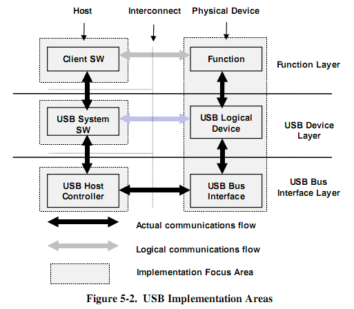
- The USB Bus Interface layer provides physical/signaling/packet connectivity between the host and a device.
- The USB Device layer is the view the USB System Software has for performing generic USB operations with a device
- The Function layer provides additional capabilities to the host via an appropriate matched client software layer
USB Host/Device Detail View
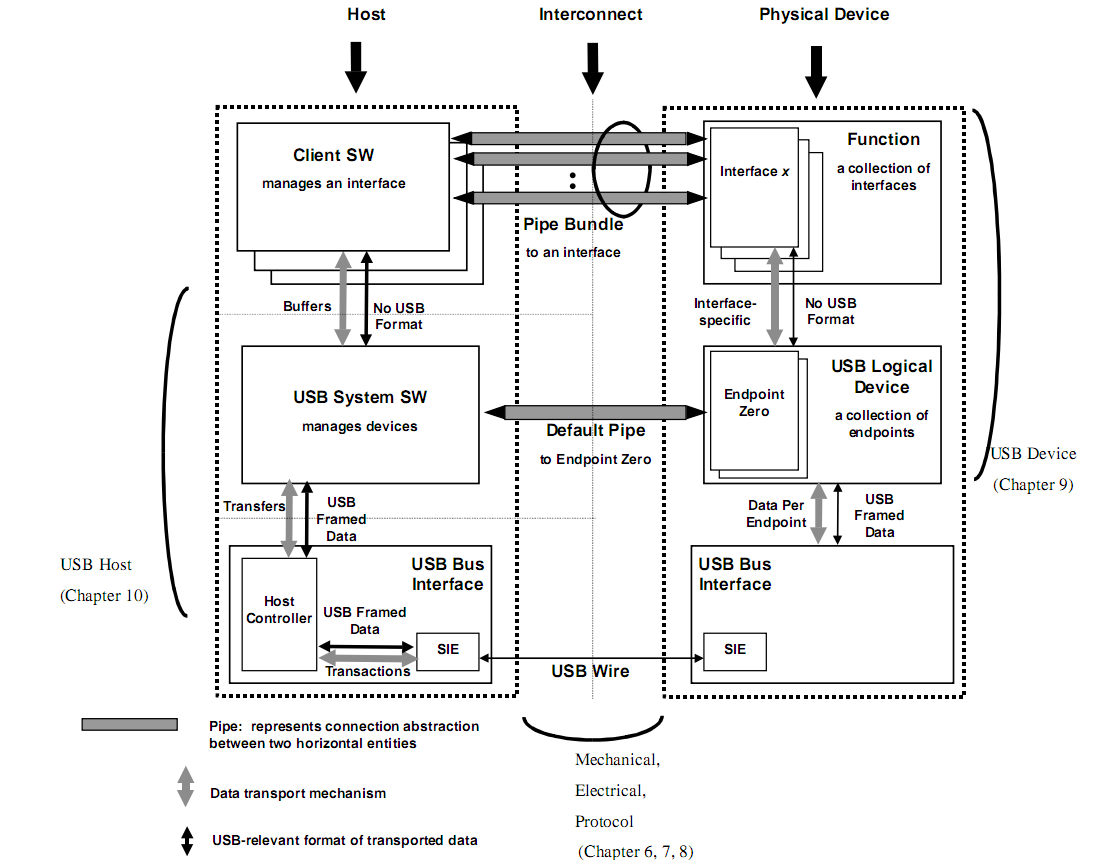
- USB Bus Interface Layer:為chip layer (皆由chip ic實現)
- USB Device Layer及Function Layer: 由kernel driver實現
USB Protocols
USB transaction consists of a
Token Packet (Header defining what it expects to follow)
Optional Data Packet, (Containing the payload)
Status Packet (Used to acknowledge transactions and to provide a means of error correction)The first packet, also called a token is generated by the host to describe
- The next packet is generally a data packet carrying the payload and is followed by an handshaking packet, reporting
Common USB Packet Fields
Data on the USBus is transmitted LSBit first. USB packets consist of the following fields,
低位元先傳送
| item | bit | note |
|---|---|---|
| Sync | 8bit / 32bit(high speed) | All packets must start with a sync field |
| 10000000B | ||
| PID | 8bit | PID stands for Packet ID |
| 只有4bit 資料 | ||
| ADDR | 7bit | 指明USB總線上1個設1備 |
| The address field specifies which device the packet is designated for. | ||
| Being 7 bits in length allows for 127 devices (Address 0 is not valid) | ||
| ENDP | 4bit | 指明USB的端點 |
| The endpoint field is made up of 4 bits, allowing 16 possible endpoints. | ||
| Low speed devices, however can only have 2 additional endpoints on top of the default pipe. (4 endpoints max) | ||
| CRC | Cyclic Redundancy Checks are performed on the data within the packet payload | |
| 有兩種: Token pkt(CRC5) , Data pkt(CRC16) | ||
| EOP | End of packet |
USB Packet Types
有四種不同package type: {Token, Data, Handshake, SOF} packets
![[PID Group]](/2016/10/24/usb/pid_type.png "[PID Group]")
| type | format |
|---|---|
| Token | Sync, PID, ADDR, ENDP, CRC5, EOP |
| Data | Sync, PID, Data, CRC16, EOP |
| Handshake | Sync, PID. EOP |
| Start of Frame | Sync, PID, FrameNum(11bit), CRC5, EOP |
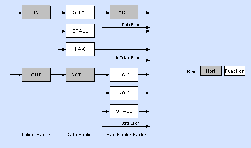
Token Packets
OUT PID: host 發送到 deivce
IN PID: device 發送到 host
Setup PID: host 向device發送配置信息Data Packets
low speed只有DATA0及DATA1
Maximum data payload size for low-speed devices is 8 bytes
Maximum data payload size for full-speed devices is 1023 bytes.
Maximum data payload size for high-speed devices is 1024 bytes.Handshake Packets
ACK PID: 說明接收已經正確接收到數據
Acknowledgment that the packet has been successfully received.
NAK PID: Reports that the device temporary cannot send or received data
STALL : 表示此端點已被挂起Start of Frame Packets
The SOF packet consisting of an 11-bit frame number is sent by the host
every 1ms ± 500ns on a full speed bus
every 125 µs ± 0.0625 µs on a high speed bus.
USB Functions
![[USB Function]](/2016/10/24/usb/usb-functions.png "[USB Function]")
host傳送pkt,裡面會指定addr=2,endpoint=1,direction=OUT
每個device,低層會依這些訊息,來決定此frame是要送給誰
若是傳送給此device, 此時會將pkt,並且copy到endpointer buffer,產生中斷
Endpoints
- Endpoints can be described as sources or sinks of data
- 當EP1 Out收到host傳來的buffer
若要回傳資料,需要等待host傳來EP1 IN,此時才能回傳資料 - All devices must support endpoint zero. (即EP0)
- receives all of the devices control and status requests
- 為何CH341及FT232沒有EP0 ?
Pipes
While the device sends and receives data on a series of endpoints, the client software transfers data through pipes.
A pipe is a logical connection between the host and endpoint(s)
pipe transfer type: Control, Bulk, Iso, Interrupt
- USB defines two types of pipes
- Stream Pipes
have no defined USB format
that is you can send any type of data down a stream pipe - Message Pipes
have a defined USB format
They are host controlled
- Stream Pipes
Endpoint Types
- 有下例四種,transfer/endpoint type
- Control Transfer
- Interrupt Transfer
- Isochronous Transfer
- Bulk Transfer
USB傳輸
USB Control Transfer (USB控制傳輸)
控制傳輸主要用于傳輸少量的,對傳輸無速率要求,但必順保證傳輸的數據
- 用於host與device之間的配置通信(device descriptor)
- 任何device順在EP0中支持control trasnfer (usb軟体通過EP0來訪問device狀態)
- 除了端點0以外,其它端點也通以支持控制傳輸
- the packet length of control transfers in low speed devices must be 8 bytes
- high speed devices allow a packet size of 8, 16, 32 or 64 bytes
控制傳輸需經過下例3個階段
- Setup Stage
- Data Stage
- Status Stage
Setup Stage
setup token is sent first which contains the address and endpoint number
由3個pkt組成
第一個Setup pkt(此含ADDR及ENDP)
第二個DATA0 pkt(此內含Device Descriptor Requst資料格式)
第三個H/S pkt
![[Setup Stage]](/2016/10/24/usb/control-tranfer-setup-stage.png "[Setup Stage]")
Data Stage (optional Data Stage)
為非必要,當無DATA時,則無此stage
再來就是接收或傳送數個Data
通常都要回傳Device Descriptor(若剛剛收到Device Descriptor Requst)![[Data Stage]](/2016/10/24/usb/control-tranfer-data-stage.png "[Data Stage]")
Status Stage
reports the status of the overall request and this once again varies due to direction of transfer.![[Status Stage]](/2016/10/24/usb/control-tranfer-status-stage.png "[Status Stage]")
- Control Read and Write Sequences
如usb 2.0說明(8.5.3 Control Transfer)
A SETUP always uses a DATA0 PID for the data field of the SETUP transaction
The Status stage of a control transfer is the last transaction in the sequence.
A Status stage is delineated by a change in direction of data flow from the previous stage and always uses a DATA1 PID.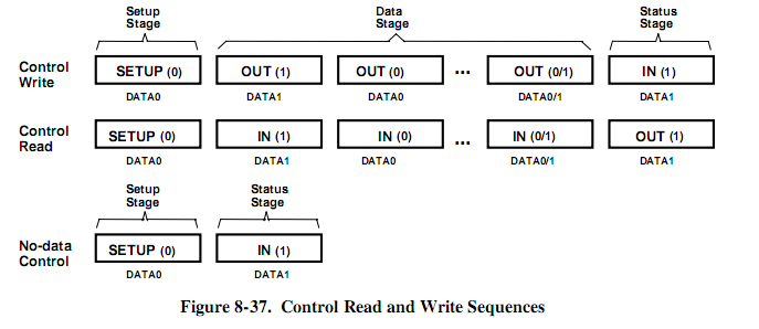
The Setup Packet
- Every USB device must respond to setup packets on the default pipe.
- 在Control Transfer在Setup Stage中要填入Data0裡面數據格式如下
![[Setup Format]](/2016/10/24/usb/setup-pkt-format.png "[Setup Format]")
Interrupt Transfers
An Interrupt request is queued by the device until the host polls the USB device asking for data.
- The maximum data payload size for low-speed devices is 8 bytes.
- Maximum data payload size for full-speed devices is 64 bytes.
- Maximum data payload size for high-speed devices is 1024 bytes.
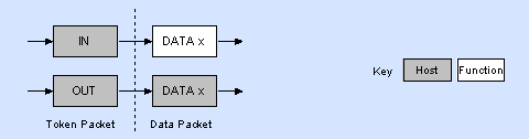
![[Interrupt Transfer]](/2016/10/24/usb/interrupt-transfer.png "[Interrupt Transfer]")
The above diagram shows the format of an Interrupt IN and Interrupt OUT transaction.
IN:
- The host will periodically poll the interrupt endpoint.
- This rate of polling is specified in the endpoint descriptor which is covered later.
- 在Endpointer Descript中會定義bInterval數接
OUT:
- When the host wants to send the device interrupt data,
- it issues an OUT token followed by a data packet containing the interrupt data.
當host準備接受中斷數據時,它將會送出IN pkt,而device將反回Datax
當host準備送出中斷數據時, 它會送出OUT pkt及Datax
Isochronous Transfers (同步傳輸)
適用於傳輸大量,速率固定且對服務週期有要求的
Isochronous transactions have a token and data phase, but no handshake phase
Isochronous Transfers provide
- Guaranteed access to USB bandwidth.
- Bounded latency.
- Stream Pipe - Unidirectional
- Error detection via CRC, but no retry or guarantee of delivery.
- Full & high speed modes only.
- No data toggling.
The above diagram shows the format of an Isochronous IN and OUT transaction
最大padload size定義於endpoint descriptor
- maximum of 1023 bytes for a full speed device
- maximum 1024 bytes for a high speed device
Bulk Transfers
Bulk transfers can be used for large bursty data.
Bulk transfers provide error correction in the form of a CRC16 field on the data payload
and error detection/re-transmission mechanisms ensuring data is transmitted and received without error.
Bulk Transfers
- Used to transfer large bursty data.
- Error detection via CRC, with guarantee of delivery.
- No guarantee of bandwidth or minimum latency.
- Stream Pipe - Unidirectional
- Full & high speed modes only.
The above diagram shows the format of a bulk IN and OUT transaction.
Bulk transfers are only supported by full and high speed devices
full speed endpoints, the maximum bulk packet size is either 8, 16, 32 or 64 bytes long
high speed endpoints, the maximum packet size can be up to 512 bytes long